Get In Touch
Get in touch with us for any questions or quotes on surveying services and products. We will respond back as soon as we can.

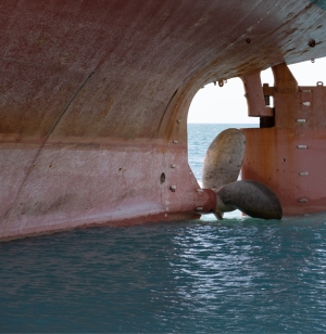
Applying Simultaneous Localization and Mapping (SLAM) methods, Zupt’s 3D Recon is used for hull/tank inspection without requiring an additional vehicle positioning solution to tie overlapping swaths of data together. 3D Recon automatically matches features between multiple vehicle passes, generating a complete spatially correct model of the exterior or interior of a submerged hull/tank. Zupt’s compact technology may be manipulated in tough-to-reach locations and oriented in any direction for efficient contactless data acquisition.
Contact Zupt today to learn more.
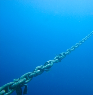
Zupt’s 3D Recon is used for contactless mooring line inspection as a more efficient alternative to the industry convention of “go, no-go” calipers for wear and simple ROV video footage. Easily manipulated by either a Work Class or Inception Class ROV, 3D Recon quickly models the mooring line or chain links to a pixel resolution of less than a millimeter to provide highly accurate models to measure chain-link wear without physically contacting the mooring line. Zupt’s deliverable provides data to be stored and compared with future surveys to automatically detect wear rates of the mooring line.
Contact Zupt today to learn more.
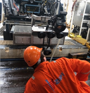
Zupt’s 3D Recon technology provides a real-time relative-to-structure positioning solution for external ROV-mounted sensors. Zupt’s 3D Recon provides a relative, sub-centimeter position to any external sensors that are also interfaced with the subsea vehicle. Necessary for many integrity management surveys, such as contactless cathodic protection, 3D Recon not only eliminates the need for a complicated ROV positioning solution for relative positioning but also provides a sparse and dense point cloud for the external vehicle sensors to overlay their data.
Contact Zupt today to learn more.
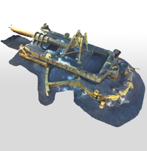
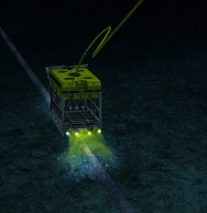
Developed specifically for integrity management surveys of subsea structures, 3D Recon generates high-resolution 3D models of any structure surveyed. This 3D deliverable provides the detail necessary to analyze corrosion, measure anode depletion, inspect anomalies, and more. 3D Recon integrates 3 machine vision cameras with an inertial navigation system in a compact 4000-meter rated subsea housing. The offshore team interfaces 3D Recon to the ROV as a standalone sensor (no external positioning solution necessary) to efficiently collect data to generate a highly accurate 3D model. 3D Recon solution provides a real-time quality control interface to provide the offshore user a simple program to determine there are no voids in the data collected.
Contact Zupt today to learn more.
Zupt’s pipeline inspection-specific technology integrates an inertial navigation system with 5 high-definition cameras to accurately model a greater area of visible pipeline and nearby seabed. In a single, efficient pass of the pipeline, the ROV or AUV flying the pipeline will collect the necessary data to generate a high-resolution point cloud or mesh model of the pipeline section along with any potential free span. The pipeline deliverable provides details on any corrosion, anomalies, length and depth of free span, anode depletion, and more. The resultant pipeline model is scalable and can be integrated with the vehicle positioning solution to provide the absolute position of the entire pipeline survey.
Contact Zupt today to learn more.
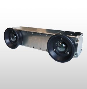
3D Recon V2 is a subsea stereo imaging system that produces high-resolution, geospatially accurate 3D models of what is seen subsea. Housed in a compact subsea enclosure rated for depths up to 4,000 meters, it features two high-resolution machine vision cameras and a high-performance MEMS IMU. By integrating inertial technology with imaging sensors, 3D Recon V2 can generate real-time sparse point clouds for navigation and quality control, as well as high-density 3D models that help engineers make informed decisions about the integrity of their subsea assets.
While 3D Recon V2 was initially developed for Integrity Management (IM) and Inspection, Repair, and Maintenance (IRM) purposes. Its versatility has since led to adoption in a range of other applications, including::
3D Recon V2 leverages the ‘3D reconstruction’ methodology, advanced computer vision, and inertial navigation techniques to generate camera poses, point clouds, object detection, and pose estimation of underwater objects. It supports both real-time and highly optimized offline dense point cloud generation. Here's how each pipeline works:
Real-Time Dense Point Cloud:
Offline Dense Point Cloud:
Real-Time Detection and Pose Estimation of Underwater Objects:
3D Recon V2 delivers high-resolution, geospatially accurate 3D models with submillimeter pixel resolution. These precise models support the subsea integrity community in making informed decisions about structural health over time. 3D Recon V2 integrates seamlessly into existing workflows, providing high-resolution still images, conventional video, and 3D models generated both in real time for verification and offline for detailed inspection.
We require a survey mux to integrate the 3D Recon V2 spread. All power, serial communications, and image data are connected to the Mux/ROV through a single PBOF cable. It relies on one RS232 and one GB Ethernet port for configuration and data transmission. Power requirements are 24Vdc at 150W.
Contact Zupt today to learn more about 3D Recon V2 and how it can enhance your subsea operations.
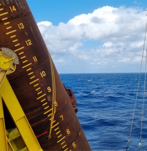
Zupt’s VertiCAM is an in-air, contactless LiDAR, camera, and inertial system designed to monitor the verticality of tubular structures such as monopiles, piles, conductors, and wind turbine foundations during installation. Installed on a vessel, the system uses two “nodes”, each including a LiDAR, HD camera, and an inertial measurement unit. Mounted up to 50 meters from the structure, VertiCAM captures pitch, roll, and heading data in real time, allowing teams to assess and adjust orientation without pausing hammering or attaching sensors to the monopile.
With its rugged design and intuitive interface, VertiCAM allows installation teams to view heading and inclination from the deck or bridge while recording each installation. It can be used alone or integrated with Zupt’s iRTS pile run monitoring system to provide immediate feedback and maintain project tolerances.
As offshore wind projects grow in scale and complexity, VertiCAM provides fast and reliable verticality feedback, reducing rework and improving outcomes. Its dual redundant sensors deliver consistent performance even in low visibility, making it a dependable solution for modern renewable energy operations.
VertiCAM is used to determine the verticality of tubular structures, with several applications in offshore renewables. These applications include:
For monitoring the pitch and roll of the pile during installation, this is how VertiCAM works:
This system is connected to an NVIDIA GPU processor running real-time verticality calculations, also providing a remote human-machine interface (HMI) processor connected to the core processor via a network (Ethernet) connection to allow remote data viewing and interface to the system.
Contact Zupt today to learn more about VertiCAM and how it can enhance your offshore operations.
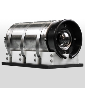
HaloCAM is a compact, 4000-meter rated sensor that delivers precise pitch, roll, heading, depth, and position for subsea structures during installation. It reduces the cost and risk of attaching expensive sensors directly to piles, conductors, or other subsea structures while ensuring accurate deployment and long-term reliability.
Inside its single 266mm x 150mm housing, HaloCAM combines an Inertial Navigation System (INS), a machine vision camera, and onboard processing. This integration provides real-time positioning and attitude data through a straightforward user interface, and the navigation engine can accept inputs from USBL, LBL, DVL, depth, or LoPs, making the system adaptable to a wide range of offshore projects. HaloCAM’s design allows it to be easily deployed on an ROV, delivering accurate updates even in challenging conditions.
By combining inertial navigation with machine vision, HaloCAM offers a reliable and efficient solution that improves safety, reduces operational costs, and enhances confidence across both oil and gas and offshore wind projects.
HaloCAM combines a high-performance IMU with an HD camera and onboard machine vision processing to deliver the positioning accuracy the industry requires.
Mounted on the front of an ROV, HaloCAM maintains a clear line of sight to simple fiducial targets placed on the structure. The system automatically acquires the targets, processes INS and camera data internally, and provides real-time position and attitude through an intuitive user interface. The ROV can maintain a 2–4 meter standoff while HaloCAM delivers consistent updates unaffected by vibration, hammering, or jetting during installation. Targets can be dimensionally controlled and placed on flat or curved surfaces.
If the ROV has absolute positioning (USBL, LBL, or LoPs), HaloCAM translates this reference frame to the structure with the same accuracy. When not used for structure positioning, HaloCAM functions as a precise subsea INS.
Contact Zupt today to learn more.
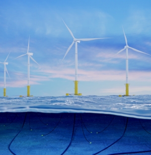
VertiCAM is a contactless camera-inertial solution that streamlines the installation process of Floating Wind Turbine Generator (WTG) foundations and turbine masts. This integrated solution determines the real-time position and verticality of structures with precision, meeting the high-accuracy installation tolerances required by floating WTG foundations and turbine masts.
When installing WTG masts from or onto floating structures, motion-compensated sensors are crucial for the WTG mast’s alignment and verticality. Zupt's VertiCAM emerges as a precise solution, ensuring the alignment and verticality of WTG masts to process positioning data independent of the motion of the installation vessel. As a contactless solution, VertiCAM offers flexibility and ease of use. Zupt’s solution does not require physical bracketry to be mounted to the mast or foundation and includes equipment that is easily mobilized and demobilized from the vessel in question.
Contact Zupt today to learn more about floating mask installation support and how it can enhance your offshore operations.
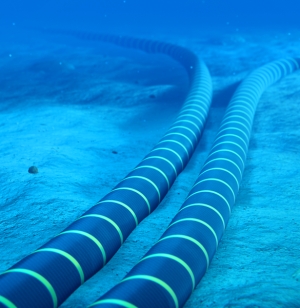
Zupt's subsea modeling system, known as '3D Recon', delivers accurate and detailed 3D models to create digital twins of newly installed or existing infrastructure, subsea transmission lines, pipeline free span, and much more. These models are geospatially correct and can offer submillimeter pixel resolution representations of subsea structures up to depths of 4,000 meters. The high-resolution models may be utilized for asset integrity, as-built models, metrology, and GVI to aid in making informed decisions on structural health.
3D Recon delivers a complete model of the structure, allowing subsea integrity engineers to have a big-picture view while also maintaining the details necessary to make decisions on the asset. Subsea engineers can then focus their attention on particular areas of interest, zooming in and navigating around the 3D model to make distance, angular, and volumetric measurements with known accuracy. This ability enables them to quickly gather detailed information about the structure's condition to assess structural integrity and facilitate proactive decision-making.
Contact Zupt today to learn more.