
FDI Creative Services, Inc.
Subsea Monopile Installation Monitoring
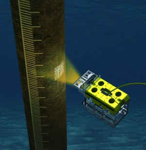
HaloCAM is a uniquely developed contactless camera-inertial solution that integrates a high-resolution machine vision camera with a navigation-grade Inertial Navigation System (INS) to provide real-time data positioning for monopiles during installation. The real-time data transmitted to the surface includes crucial parameters such as altitude, inclination, roll, pitch, and relative heading of the target concerning the Remotely Operated Vehicle (ROV).
HaloCAM proves instrumental in the installation of monopiles subsea for offshore wind farms, where precise installation is crucial for the overall efficiency of renewable wind energy generation. These monopiles, ranging from 5 to 7 meters in diameter, are driven into the seabed and serve as the sturdy foundation for supporting wind turbines that will later be installed on top. The verticality of these monopiles significantly impacts the structural integrity and longevity of the wind turbines; because of this demand for precise verticality, there are highly accurate installation requirements from operators. HaloCAM serves as a tool for overcoming these challenges to achieve these accuracy demands.
HaloCAM is a standalone and contactless system mounted to an ROV. HaloCAM combines machine vision camera data with the ROV positioning solution to determine the absolute position of the structure to the same level of positional accuracy as the subsea vehicle (USBL or LBL) positioning.
With its contactless capabilities, HaloCAM can precisely measure the attitude and differential depth of a target positioned on any monopile. This marks an advancement in the Renewable Energy sector, as it eliminates the need for time-consuming/laborious and hazardous manual installation of bracketry typically required for subsea gyros or acoustic transponder buckets in traditional methods.
Benefits of Contactless Subsea Monopile Installation
- No specialized personnel required offshore, remote operation capable
- Single, self-contained unit with simple interfacing
- No lever arms to calibrate between the INS and camera
- Easy dimensional control (DC) of targets to casing—while casing is horizontal
- Deployable on small or work-class ROVs
Contact Zupt today to learn more about subsea monopile installation applications and how they can enhance your subsea operations.
In-Air Monopile installation
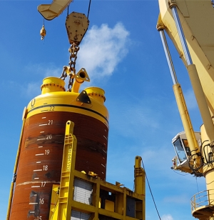
Installing monopiles for offshore wind farms demands precise real-time monitoring of inclination and position. Traditionally, during installation, a crane on the vessel lowers the foundations into the sea, and a hydraulic hammer drives the monopiles into the seabed. This method includes physically mounted bracketry and sensors, which can be costly and pose safety risks. Zupt developed VertiCAM, a contactless solution using an LiDAR-camera method, to address these challenges and install in-air, reducing costs and safety concerns.
By integrating LiDAR (Light Detection and Ranging), inertial measurement units (IMUs), and camera sensors, VertiCAM is a robust and redundant sensor package that provides highly accurate measurements at the offset to the structure of up to 50 meters. With real-time monitoring of monopile verticality throughout the installation process, any deviations from the desired attitude or position are immediately detected, allowing for corrections if necessary.
The Benefits of In-Air Monopile Installation
- Contactless Data Collection: Streamlining installation procedures, our solution eliminates the necessity for physical brackets and sensors attached to monopiles.
- Real-Time Monitoring: Achieve accuracy and precision with complete visibility into the verticality of your monopiles throughout the installation process.
- Enhanced Safety: Prioritize the safety of offshore operations by eliminating the risks associated with physical sensor installations.
Contact Zupt today to learn more about in-air monopile installation applications and how they can enhance your offshore operations.
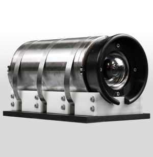
3D Recon V2
3D Recon V2 is a subsea stereo imaging system that produces high-resolution, geospatially accurate 3D models of what is seen subsea. Housed in a compact subsea enclosure rated for depths up to 4,000 meters, it features two high-resolution machine vision cameras and a high-performance MEMS IMU. By integrating inertial technology with imaging sensors, 3D Recon V2 can generate real-time sparse point clouds for navigation and quality control, as well as high-density 3D models that help engineers make informed decisions about the integrity of their subsea assets.
3D Recon V2 Applications
While 3D Recon V2 was initially developed for Integrity Management (IM) and Inspection, Repair, and Maintenance (IRM) purposes. Its versatility has since led to adoption in a range of other applications, including::
- Jumper/Spool Metrology
- Mooring Chain Link Inspection
- Hull Inspection
- Pipeline Out-Of-Straightness (OSS) Surveys
- Pre-Install/As-Built Documentation
- Real-Time Relative-to-Structure Positioning
- Real-Time Object Detection and Pose Estimation of Underwater Objects
How 3D Recon V2 Works
3D Recon V2 leverages 3D reconstruction and photogrammetry methodologies, advanced computer vision, and inertial navigation techniques to generate accurate camera poses and high-resolution point clouds of subsea assets. It supports both real-time reconstruction and highly optimized offline dense point cloud generation. Here's how each pipeline works:
Real-Time Dense Point Cloud:
- Alignment: IMU data determines the sensor's orientation (heading, pitch, roll).
- Feature Detection: Cameras capture images at 5-10Hz, and features are identified based on intensity variations.
- Feature Matching: Descriptor vectors are computed for features and used for matching between stereo cameras and sequentially from frame to frame, creating a sparse point cloud (approximately 5-10cm pixel resolution).
- Navigation Integration: The navigation engine integrates acceleration and angular velocity data to update navigation states (position, velocity, attitude).
- Global Matching: Matching features with existing ones in the map occurs.
- Position Projection: Features are projected from the camera frame to the global frame.
- Consistency Checks: Checks ensure alignment with the global map, utilizing RANSAC and optimization.
- Navigation Update: Successful feature matches update the state and covariance; new features are added to the map.
- Path Optimization: Data collection for map optimization involving keyframes triggered by specific events.
- Dense Point Cloud Generation: High-density point clouds are generated using computed position and orientation and utilize disparity maps created by comparing light intensity between the left and right cameras.
- SLAM: Camera pose, trajectory estimation, and dense point cloud generation occur in real time, allowing the operator to see their position relative to the structure, track their path, and assess coverage. When previously mapped areas are revisited, a loop closure event is triggered, correcting accumulated drift in camera pose and trajectory to ensure globally consistent dense point clouds.
Offline Dense Point Cloud:
- Feature Detection: Similar to the real-time dense pipeline, this pipeline also detects features from every image captured by the cameras but extracts higher-quality features than the real-time dense pipeline.
- Feature Matching: Descriptor vectors are computed for features and used to match every image collected. Unlike the real-time dense pipeline, this pipeline also performs non-sequential image matching.
- Structure from Motion: Structure from Motion and Bundle Adjustment algorithms are utilized to optimally estimate the 3D positions of features and the camera poses for each captured image. This process creates a sparse 3D point cloud along with the estimated camera poses at the time each image was taken.
- Dense Point Cloud Generation: High-density point clouds are generated using computed camera poses and disparity maps created by comparing light intensity between patches around sparse features across all images.
- Mesh Generation: Once the dense point cloud is generated, surface normals are computed for each point using its three nearest neighbors, which define a local plane. This process results in a highly detailed 3D model of the structure.
Real-Time Detection and Pose Estimation of Underwater Objects:
- Deep Learning model training: State of the art Deep Learning models are trained using collected and annotated data to recognize a certain object. The model learns to detect the object and generate bounding boxes and confidence scores of its predictions.
- Keypoint prediction: The model and pipeline also generate specific ‘Key Points’ used for pose estimation.
- Pose Estimation: Using known correspondences between the 2D Key Points and the corresponding object’s dimensions, the pose of the object relative to the cameras are calculated using the Perspective-n-Points algorithm.
3D Recon V2 Key Features
- Linear, Angular, and Area Accuracy: Because of the tightly coupled inertial navigation solution, 3D Recon V2 offers accurate spatial scaling within the dense delivered models. This precision ensures reliable data for measurement-based assessments.
- Change Detection: One of the key advantages of 3D Recon V2 is its ability to automate change detection. Automated Change Detection is a powerful feature that becomes accessible through the utilization of models generated by 3D Recon V2. By comparing historical 3D models, operators can monitor structural changes over time for proactive IM decisions.
- Additional Sensor Integration: 3D Recon V2 can integrate data from other sensors (Contactless CP, hydrocarbon sniffers, etc.), providing a comprehensive model or heat map for structural integrity analysis.
Deliverables of 3D Recon V2
3D Recon V2 delivers high-resolution, geospatially accurate 3D models with submillimeter pixel resolution. These precise models support the subsea integrity community in making informed decisions about structural health over time. 3D Recon V2 integrates seamlessly into existing workflows, providing high-resolution still images, conventional video, and 3D models generated both in real time for verification and offline for detailed inspection.
Data Acquisition Requirements
We require a survey mux to integrate the 3D Recon V2 spread. All power, serial communications, and image data are connected to the Mux/ROV through a single PBOF cable. It relies on one RS232 and one GB Ethernet port for configuration and data transmission. Power requirements are 24Vdc at 150W.
Product Specs
- Type of Application – Marine
- Year of Introduction – 2020
- Length - 77.9 cm
- Width - 59.4 cm
- Depth - 30.0 cm
- Weight in Air - 34Kg
- Weight in Water - 23Kg
- Power Requirement - 24VDC 6A / 150W
- Serial Communications - RS232 (230400 bps)
- Housing – Titanium
- Rated - 4,000 m
- Sensor Type - Active Pixel CMOS, Global Shutter Resolution - 2028 x 2448
- FoV Horizontal - 85°
- FoV Vertical - 65°
- Number of Frames Per Second - 5 - 10 fps Copper & 10 - 20 fps SM Fiber
- Start Up Time - 0.02 s
- Communication - 1 Gbps Ethernet Copper & 10 Gps
- SM Fiber - Single Fiber Channel
- Software – Included
- Export Image Formats - Color palletized Mesh, Point Cloud *.ply (Binary)
- Battery Type - No Battery
Real-Time Dense Reconstruction
Automated Object Detection
3D Recon V2 Latest Advancements Presentation with Danny Tapper
Contact Zupt today to learn more about 3D Recon V2 and how it can enhance your subsea operations.
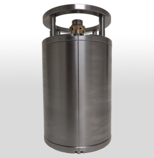
HaloCAM
HaloCAM is a compact, 4000-meter rated sensor that delivers precise pitch, roll, heading, depth, and position for subsea structures during installation. It reduces the cost and risk of attaching expensive sensors directly to piles, conductors, or other subsea structures while ensuring accurate deployment and long-term reliability.
Inside its single 266mm x 150mm housing, HaloCAM combines an Inertial Navigation System (INS), a machine vision camera, and onboard processing. This integration provides real-time positioning and attitude data through a straightforward user interface, and the navigation engine can accept inputs from USBL, LBL, DVL, depth, or LoPs, making the system adaptable to a wide range of offshore projects. HaloCAM’s design allows it to be easily deployed on an ROV, delivering accurate updates even in challenging conditions.
By combining inertial navigation with machine vision, HaloCAM offers a reliable and efficient solution that improves safety, reduces operational costs, and enhances confidence across both oil and gas and offshore wind projects.
Benefits
- No specialized personnel required offshore, remote operation capable
- Single, self-contained unit with simple interfacing
- No lever arms to calibrate between the INS and camera
- Easy dimensional control (DC) of targets to casing—while casing is horizontal
- Deployable on small or work-class ROVs
Applications
- Well spudding
- Conductor casing installations
- Offshore wind farm monopiles
- Suction pile installations
Accuracy
- Heading: ±0.15° sec Lat.*
- Pitch & Roll: ±0.1°
- Positioning: Same as USBL/LBL *Requires DC of targets to the structure
How HaloCAM Works
HaloCAM combines a high-performance IMU with an HD camera and onboard machine vision processing to deliver the positioning accuracy the industry requires.
Mounted on the front of an ROV, HaloCAM maintains a clear line of sight to simple fiducial targets placed on the structure. The system automatically acquires the targets, processes INS and camera data internally, and provides real-time position and attitude through an intuitive user interface. The ROV can maintain a 2–4 meter standoff while HaloCAM delivers consistent updates unaffected by vibration, hammering, or jetting during installation. Targets can be dimensionally controlled and placed on flat or curved surfaces.
If the ROV has absolute positioning (USBL, LBL, or LoPs), HaloCAM translates this reference frame to the structure with the same accuracy. When not used for structure positioning, HaloCAM functions as a precise subsea INS.
Contact Zupt today to learn more.
MicroTTU
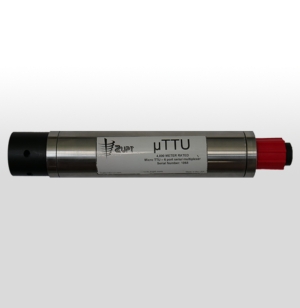
The microTTU is a compact subsea serial multiplexor that turns one ROV serial channel into six additional channels for added comms on ROV, AUV, or towfish operations. It is built for harsh subsea use and is depth rated to 4,000 m. Data multiplexed subsea is available topside on a physical COM port or as a virtual COM port for other applications.
Each sensor port is fully configurable from the surface with independent baud rate and parity, and settings stored in NVRAM. Operators have transparent control of sensors, plus software and hardware break commands. Data can be appended with precise time tagging or passed through unchanged, and the surface software can log individual channels to separate files.
Configuration options include six RS232 channels or a mix of four RS232 and two RS422. The uplink is normally RS232, with RS422 or RS485 available for long hard-wired use. Key specs: input 16 to 30 Vdc, about 2 W for the unit, up to 100 W available for sensor power, depth rating 4,000 m, connectors MCBH8M (uplink) and MCBH16M (sensors), length 305 mm, diameter 50 mm, weight 2.6 kg in air and 2 kg in water.
Specifications
- Depth rating: 4,000 m
- Power input: 16–30 VDC
- Power draw: ~2 W for unit, up to 100 W available for sensors
- Uplink options: RS232 standard; RS422 or RS485 available
- Dimensions: 305 mm length × 50 mm diameter
- Weight: 2.6 kg in air, 2.0 kg in water
- Connectors: MCBH8M (uplink), MCBH16M (sensors)
Highlighted Features
- Six configurable serial sensor ports (RS232 standard, optional RS422)
- Transparent sensor communication with surface control
- Independent baud rate and parity settings per port
- Break command support (software and hardware)
- NVRAM storage for saved configurations
- Time-tagging available for accurate data synchronization
- Surface software with per-channel logging
Application Advantages
- Expands ROV, AUV, or towfish capability with minimal hardware
- Streamlined integration through virtual or physical COM ports
- Compact, lightweight design reduces vehicle payload impact
- Reliable subsea performance with low power requirements
Contact Zupt today to learn more.
Fusion Splice
Fusion-Splice is a cutting-edge solution that bridges acoustic and inertial navigation systems for marine survey operations. It delivers real-time integration of Sonardyne LBL ranging data directly into an iXBlue inertial navigation platform—enabling high-precision positioning even when you don’t have a complete system suite from one manufacturer.
Designed to be both powerful and cost-efficient, Fusion-Splice works with the gear you already have. Its rack-mount configuration, RS-232 and USB ports, and compatibility across 9,600 to 115,200 bps communication rates mean you can deploy it without reengineering your entire setup. It draws under 5 watts of power and supports standard AC inputs (110-220Vac), so it's easy to add into existing subsea workflows.
With Fusion-Splice, you gain workflow flexibility and major time savings for sparse LBL operations. Whether you’re conducting scientific research, commercial survey work, or oil & gas inspection, this product streamlines integration, reduces capital outlay, and enables accurate, reliable positioning—even when full equipment spreads aren’t possible.
Summary:
- Fusion-Splice enables real-time interfacing of Sonardyne LBL (Long BaseLine) ranges into an iXBlue Inertial Navigation System.
- Designed for Sparse LBL operations, i.e. situations where you don’t have a full complement of equipment from a single manufacturer. It lets you use the acoustic and inertial systems you already own.
- Saves time & resources by allowing operators to integrate (fuse) equipment they already have rather than buying all new or from one manufacturer.
- Facilitates flexibility in subsea workflows where full LBL spreads may not be available.
Technical Specifications
- Power Supply: 110Vac-220Vac, <5W
- Communications Ports: Standard DB9 RS-232 ports
- Communication rates: RS-232 at 9,600 - 115,200 bps
- USB Configuration: Type B port
- Size/Form Factor: 2U × 19-inch rack mount
Contact Zupt today to learn more.
Halo
Halo is a compact, easy to integrate, and affordable INS solution for ROV navigation and positioning. Halo is offered in two heading accuracy configurations: An “Affordable” <0.3° secant lat. heading accuracy INS or a “Precise” <0.1° secant lat. heading accuracy INS. Both Halo configurations are rated for use in water depths up to 4,000 meters and can tightly integrate various positioning solutions (USBL, DVL, LBL, Depth, etc.) as a complete subsea INS solution.
Contact Zupt today to learn more.
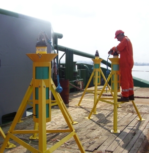
Buoy Set
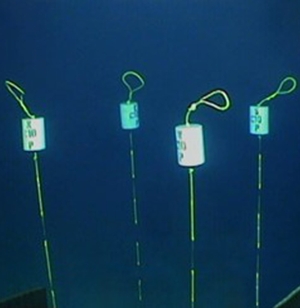
Zupt’s highly accurate Inertial Navigation System (C-PINS) and specialized buoy setting tool reduces the amount of time required to position a buoy pattern on the seabed prior to spudding a new well, placing a new subsea structure, or installing a monopile. Our methodology requires that the ROV team positions a single tool to provide precise locations for the four corner marker buoys to be placed. The tool is easily removed without disrupting the buoy markers and has a convenient, easy-to-access C-PINS receptacle.
Contact Zupt today to learn more.
Array Planning
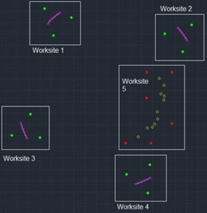
Array planning for optimizing the number of transponders deployed and calibrated on the seafloor. Zupt’s offshore surveyors and engineers offer their expertise for initial LBL array design or for a second opinion. Optimizing the acoustic array for small or large projects will not only reduce the number of assets on the seabed, but also the operational time required to deploy and calibrate the LBL array.
Contact Zupt today to learn more.
Sparse LBL
Sparse LBL is a precise subsea positing technique that couples LBL with INS technology for efficient subsea navigation. With over a decade of experience integrating INS with aiding sensors, our Sparse LBL service saves time from deploying and calibrating a full LBL array at each subsea worksite. With the same precision as LBL arrays in half the time, Sparse LBL provides higher value to your high accuracy seafloor survey operations.
Contact Zupt today to learn more.