In all that we do, we make your operational success simple by developing solutions that are more efficient and easier to use. Our mission is to deliver quality results faster, through our cutting-edge technologies that work.
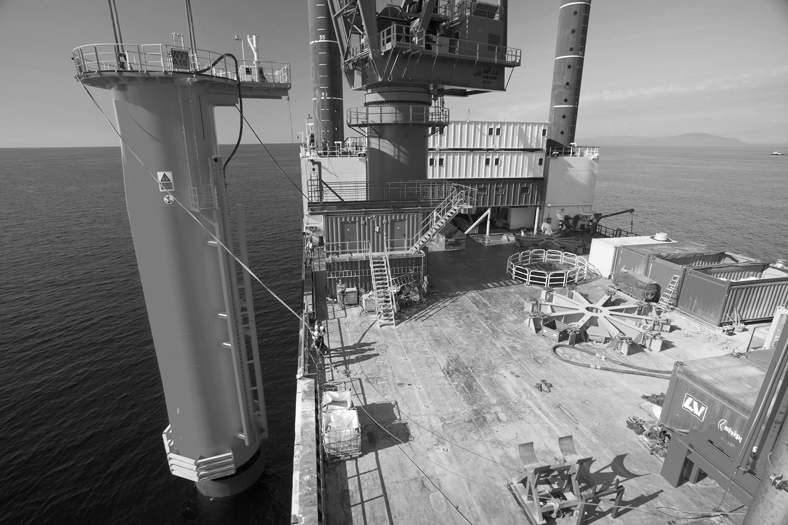
Zupt's Positioning Solutions for Offshore Monopile Installation
Zupt's Positioning Solutions for Offshore Monopile Installation
The growing demand for renewable energy has led to the development of offshore wind farms, which have become increasingl...
Optimizing Operations for Short Lead Time Requests
Optimizing Operations for Short Lead Time Requests
Button
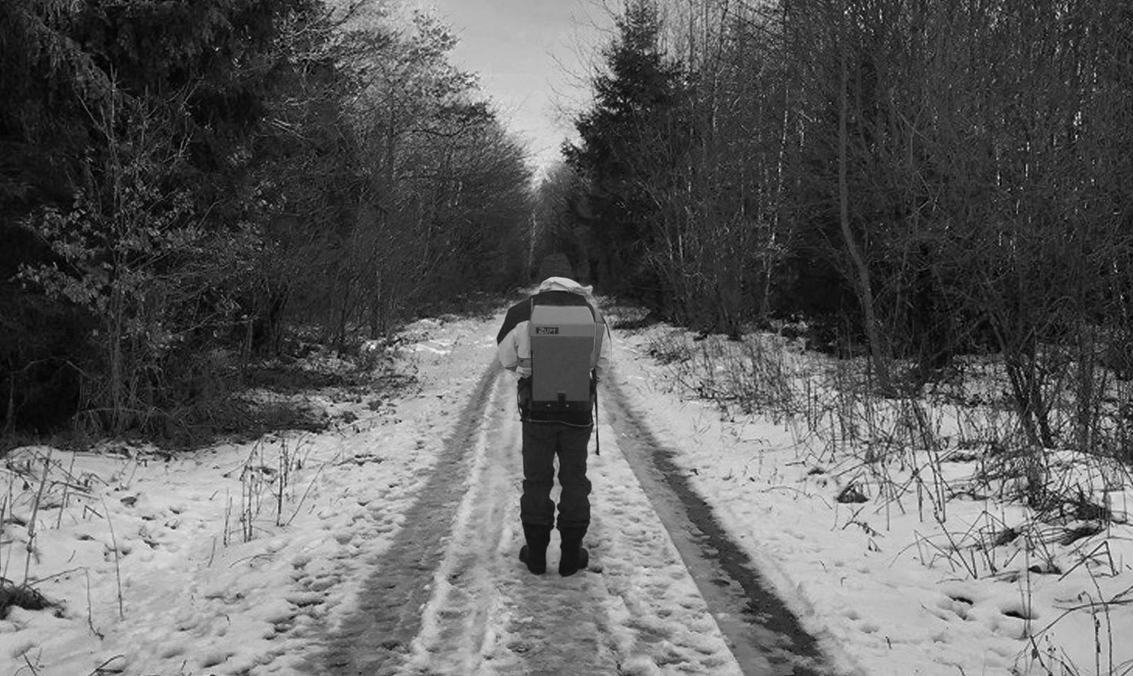
By owning and manufacturing our equipment, Zupt has a unique advantage as an energy survey contractor. This ad...
Join Zupt as an Offshore Survey Engineer!
Join Zupt as an Offshore Survey Engineer!
Are you eager to kickstart your career in offshore surveying? Zupt, a leading surveying services company, is hiring Offs...
Zupt Secures First Major Renewable Contract for Offshore Wind Farm Development
Zupt Secures First Major Renewable Contract for Offshore Wind Farm Development
Zupt just announced winning its first major renewables contract for a unique offshore wind farm development offshore the...
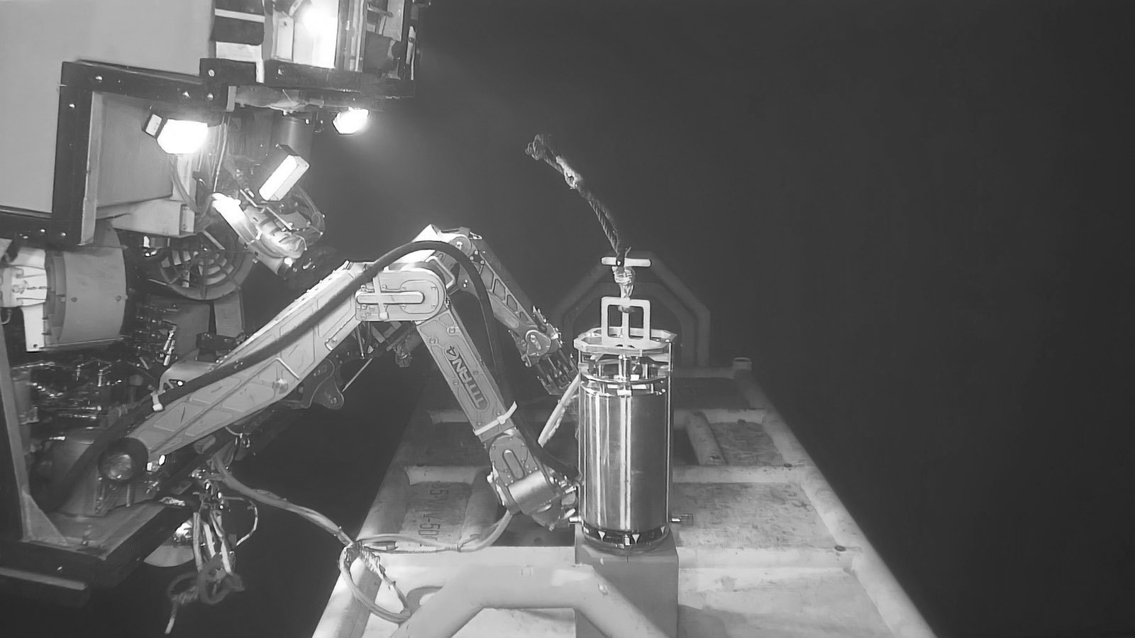
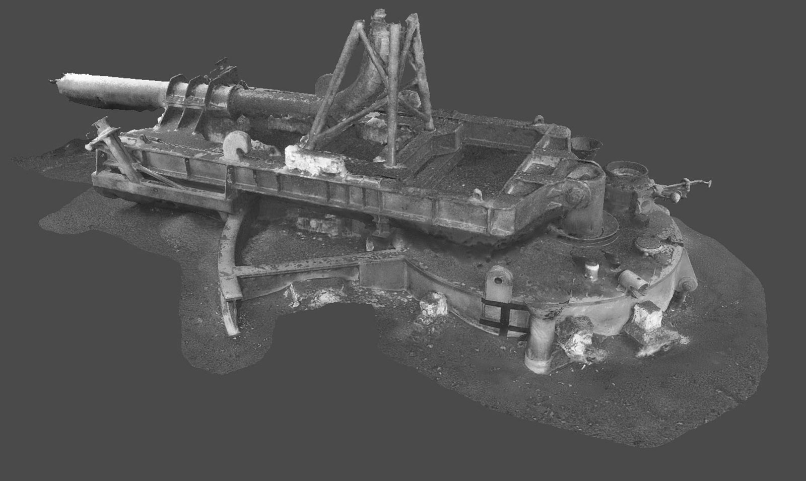
Digital Twin Generation Using 3D Recon
Digital Twin Generation Using 3D Recon
In this video, Keith discusses the powerful use of Zupt's 3D Recon technology for digital twin generation. These high-re...
Free Quote Text
Get In Touch
Get in touch with us for any questions or quotes on surveying services and products. We will respond back as soon as we can.